Article Text

Abstract
The paper explains the most important parameters for the use of colour and power Doppler in rheumatology. Recommendations for machine settings are given. The commonly encountered artefacts and their importance for image interpretation are explained.
Statistics from Altmetric.com
Most musculoskeletal ultrasound (US) is performed using grey-scale US, but newer US techniques include the use of Doppler US in the assessment of changes in tissue vascularisation that may occur in inflammatory conditions.1–3 The Doppler evaluation provides useful clinical information regarding the presence or absence of flow. Guidelines have been suggested by the European League Against Rheumatism (EULAR) work group for the use of grey-scale US in musculoskeletal disease.4 The guidelines address technical issues, training and standardisation of image acquisitions. However, no such guidelines exist for Doppler US. Standardisations of the methods for evaluating inflammation and the effect of the quality of the machine and image processing still need to be established.
Correct interpretation of flow images requires knowledge of physical and technical factors that influence the Doppler signal. Artefacts caused by physical limitations of the modality or inappropriate equipment settings may result in displayed flow conditions that may differ considerably from the actual physiological situation. As a consequence, artefacts in Doppler imaging may be confusing and lead to misinterpretation of flow information.
In this paper, we review colour Doppler and power Doppler (PD) US, as well as the artefacts and settings relevant for musculoskeletal US in rheumatology with focus only on soft tissue and joint inflammation.
DOPPLER SIGNAL
The Doppler effect is a change in wavelength (frequency) of sound resulting from motion of a source, receiver or reflector. As the US transducer is a stationary source and receiver, the Doppler effect arises from reflectors in motion—for all practical purposes these are the erythrocytes. When a pulse is reflected from erythrocytes, the frequency of the wave received differs from that, which is transmitted. This difference is known as the Doppler shift, named after the Austrian physicist and mathematician Chr. Andreas Doppler, who first described the phenomenon for light in 1843.5
There are two successive Doppler shifts involved. First, the sound from the stationary transmitting transducer is received by the moving erythrocytes. Second, the erythrocytes act as moving sources as they re-eradiate the US back toward the transducer, which is now the stationary receiver. These two Doppler shifts account for factor 2 in the Doppler equation:

where: fD is the Doppler shift, ft is the transmitted frequency, fr is the received frequency, v is the blood velocity, θ is the insonation angle (the angle between the US beam and the blood flow), and c is the speed of sound. The Doppler shift is thus directly proportional to the velocity of the flow, v, cosine to the insonation angle, θ, and the transmitted frequency of the US, ft.6
Pulsed Doppler
The Doppler circuitry determines the change in frequency indirectly. With a series of pulses the phase of the returning signals are compared with the phase of the emitted signal. A change in phase translates to a change in frequency; eg, when the returning signal is compared with the emitted one, wave tops will not meet wave tops because the distance between wave tops has changed. The number of these pulses per second is called the pulse repetition frequency (PRF).
Insonation angle, Doppler angle
This is the angle between the path of the Doppler pulses and the direction of flow in the vessel. When this angle is 90°, there will be no frequency shift as can be seen from the equation above: cos(90°) = 0. The maximum frequency shift of a given vessel is obtained when the direction of flow matches the direction of the Doppler pulses (Doppler angle = 0, flow directly towards or away from the transducer).
Blood velocity versus Doppler shift
The Doppler circuitry determines the change in frequency and, this may only be translated into a blood velocity if the insonation angle is recorded and is included in the calculation. Nevertheless, all newer equipment report blood velocities (both in spectral Doppler and on the colour bar) assuming that the Doppler angle is zero. This is, however, more often wrong than right and we are in fact dealing with frequency information unless angle correction has been performed (the process of informing the machine of the insonation angle). Angle correction is only possible in spectral Doppler and is not an issue in a rheumatological setting.
COLOUR DOPPLER, VELOCITY DOPPLER AND COLOUR FLOW MAPPING
In colour Doppler, real-time presentation of flow information in colour is superimposed on the grey-scale morphological image.
In colour Doppler, analysis is performed in the colour box, which is divided into cells. Each cell behaves like an independent Doppler gate with its own Doppler analysis. The mean frequency shift for each cell is computed and displayed as a colour. The colours that arise from the detected Doppler shifts primarily indicate qualitative direction of flow. Generally, red is used to indicate a flow towards the transducer and blue away from the transducer. Different hues of red (or blue) indicate different velocities (in reality different frequency shifts). Lighter hues are used to indicate higher frequency shifts.
Interpreting the colours
The Doppler circuitry merely detects movements up and down in the image plane. A dark red spot may therefore be blood moving slowly, directly towards the transducer or blood moving quickly at an angle close to 90°. As we generally do not know the insonation angle to the vessels we cannot compare velocities between vessels. In rheumatological use, where the tortuous vessels are seen as colour spots when they traverse the scanning plane, the so-called relative velocity information (different hues indicating different velocities) is not present.
POWER DOPPLER (ENERGY DOPPLER)
PD displays power of the Doppler shift in each cell instead of the mean frequency shift. This gives PD a theoretical advantage over colour Doppler with regard to sensitivity. Disregarding direction of flow (negative or positive frequency shift) and disregarding velocity (high or low frequency shift) the power (energy) of the many different frequency shifts inside a cell are added to form the power signal. The power mode does not measure velocity or direction and is very sensitive to flow. Therefore, it is almost angle independent and without aliasing.7
CHOICE OF DOPPLER MODE
For use in rheumatology, it is the amount of colour pixels that is of interest and not the relative velocity or direction.
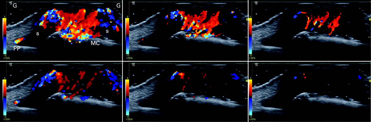
The issue when choosing Doppler modality in a rheumatological setting is the sensitivity for flow. The theoretical advantage of PD in sensitivity has disappeared in the newer high-end machines where the trend is that colour Doppler now is more sensitive than PD (fig 1). A satisfactory explanation for this has not been put forward.

In less expensive equipment, PD has the highest sensitivity. The choice between colour and PD depends on the equipment.
The machine should be set for maximum power output. A possible adverse effect of US in general and Doppler in particular is only an issue in prenatal US. In the following, the description of settings and artefacts apply to both colour and PD unless otherwise stated.
DOPPLER PARAMETERS
The most important adjustable parameters are Doppler frequency, Doppler gain, PRF, colour priority, filter, focus, persistence, colour box position and size. Patient positioning and scanning technique further influence the quality of the Doppler examination.
Doppler frequency
A lower Doppler frequency will allow more penetration but also a more grainy Doppler image (larger colour pixels). Thus, higher Doppler frequency gives a more detailed image of the vessels but at the expense of penetration.
The trade-off between penetration and sensitivity is somewhat unpredictable and resolution is in this context really not an issue. The ability to depict slow flow in a small vessel (with a weak Doppler reflection) is enhanced by a lower frequency (because the weak reflection has more penetration) but is also enhanced by a higher frequency because the Doppler shift is higher (if the reflection is powerful enough to penetrate). The unpredictability is illustrated in fig 2.

The optimum frequency must be found in practice and not in theory.
Colour box
The numerous Doppler analyses inside the colour box are quite demanding on computing power of the US unit. The frame rate goes down when colour is added and in order to obtain as live an image as possible (high frame rate) it is therefore generally recommended to make the box as small as possible.
We do, however, recommend always letting the box go to the top of the image in order to be aware of reverberation artefacts (see reverberations).
Scale and pulse repetition frequency
PRF is the Doppler sampling frequency of the transducer and is reported in Hz. The maximum Doppler shift frequency that can be sampled without aliasing is PRF/2, which is called the Nyquist limit.8 The Nyquist limit may be presented on-screen as a blood velocity (the maximum measurable velocity of blood moving directly towards or away from the transducer) or in Hz (maximum measurable Doppler shift). If the blood velocity is above the Nyquist limit, the machine will misinterpret the velocity and aliasing will occur. This is not an issue with PD.
The sensitivity of both colour Doppler and PD is affected by PRF adjustments. When a high PRF is chosen it is assumed that the investigator is interested in high velocities, and therefore filters that remove low flow to remove noise are applied (so-called linked controls). Selecting a high PRF therefore makes the system insensitive to lower velocities because of the linked controls.
In rheumatology, we wish a high sensitivity to any flow and therefore use a low PRF because the machine then will apply the lowest possible filters.
Colour priority (threshold)
When colour information is obtained, grey-scale information will often also be present and the machine has to decide whether to show one or the other. Colour priority is a function that makes this decision for the machine. This function allows valid grey-scale information to override false Doppler information, eg, it helps suppress motion artefacts in the relatively hyperechoic tissue surrounding a pulsating artery (above a certain grey level, grey overrides colour). This function also allows supposedly valid Doppler information to override false grey-scale information, eg, inside vessels colour overrides the relatively weak grey-scale reverberation artefacts (below a certain grey level colour overrides grey) (fig 3). This function explains why some Doppler artefacts apparently prefer to appear in dark regions of the image. It also explains why grey-scale gain may influence the amount of colour in the image (increasing grey-scale gain may result in more grey information being above the threshold where colour is suppressed).

In rheumatology, we often evaluate vessels that are not visible on grey-scale US, and colour priority must be maximised (be set so that grey does not override colour).
Filters
Every Doppler instrument has high-pass filters, which eliminate the lowest Doppler shifts from the display. The Doppler shifts originate from motion of the vessel wall and solid tissue. These unwanted shifts are referred to as clutter or motion artefacts. The filters—also called wall filters—may, however, eliminate signals from low velocity flow as the filters separate by frequency alone.9 10 The PRF and wall filter are linked controls—the lowest possible wall filter is lower for a low PRF than a high.
The filters should be kept at their lowest setting for use in rheumatology.
Gain
The Doppler gain is independent of grey-scale gain. The gain setting determines the sensitivity of the system to flow. By lowering the gain, noise and motion artefacts may be prevented but weak flow signals will go undetected.11 A gain setting that is too high results in random noise.12 It is appropriate to set the Doppler gain by turning it up until random noise is encountered and then lowering it until the noise disappears.11
Persistence
Persistence is a function that averages colour information over a number of frames. Most brochure images are made with maximum persistence because this results in all colour information over time being displayed in one image. All vessels are then filled with colour. The dynamic nature of flow is, however, lost. With low or no persistence the high or low resistance nature of arterial flow may be seen as blinking colour foci or colour foci with pulsating intensity, respectively.
In a rheumatological setting there is no advantage with high persistence.
Patient positioning
The patient must be positioned comfortably, and the area under investigation must be completely relaxed; otherwise, tension in the muscles and tendons will produce slight tremor resulting in movement artefacts. When scanning the hand and elbow regions, the arm should not rest on the abdomen or thorax because of respiratory movement. Some patients should also keep quiet during the Doppler examination because the voice itself may produce movement artefacts and because some patients cannot talk without involuntary movement of the hands.
All of these considerations also apply to the examiner. The scanning arm and hand must rest in a comfortable way.
Scanning technique
Most important in Doppler examinations is that very little pressure should be applied by the transducer. The pressure will affect the haemodynamics with resulting decreased flow. The use of generous amounts of scanning gel with visible gel between the transducer and skin will ensure light pressure.
ARTEFACTS
Random noise
Random noise is produced in all electrical circuits. When the gain is too high, this noise becomes detectable in Doppler circuitry. In the image it is seen as colour foci appearing randomly in the image. It is easily identified as an artefact because the colour foci do not reappear in the same location as true flow does.
The random noise is used to set the Doppler gain. A correct setting is at or just below the level that generates a little random noise.
Aliasing
This is one of the most well known artefacts in both colour and spectral Doppler examinations and arises when the Doppler shift is higher than half of the PRF (Nyquist limit). Aliased signals are displayed with the wrong directions (red instead of blue and vice versa) and with incorrect relative velocity (the hue of the colour). Aliasing cannot occur in PD.
Aliasing is not important in rheumatology and should not be avoided by increasing the PRF. This would lead to under-detection of flow because of decreased sensitivity to slow flow.
Motion
Movement of the patient, transducer or movement of the tissue or vessel wall caused by arterial pulsation during Doppler imaging give motion relative to the transducer and produce a Doppler shift.12 The movements are slow and produce low frequency Doppler shifts10 that appear as random short flashes of large confluent areas of colour.
One way to avoid these low frequency flash artefacts are by means of filters, eg, wall filters. Such filters, however, also remove information from slow moving blood.10 When the Doppler is at its highest sensitivity just at or below the noise level, intermittent motion artefacts must be accepted.
Motion artefacts are minimised when the patient is comfortably positioned with the area under investigation resting and it is also mandatory that the examiner’s scanning arm is resting comfortably as well.
Mirror
Any highly reflecting smooth surface may act as an acoustic mirror and the Doppler image is just as prone to mirroring as the grey-scale image. In rheumatology, the mirrors will nearly always be bone surfaces. The mirror artefact is easily seen as such when the true image as well as the mirror and mirror image are all in the image (fig 4). The mirror image is slightly trickier when only the mirror and mirror image are present.

In rheumatology, Doppler mirror images will more or less always show false flow below a bone surface.
Blooming
The blooming artefact describes the phenomenon that the colour reaches beyond the vessel wall making the vessels look larger than they really are (fig 5). It is gain dependent and lowering the Doppler gain will decrease the blooming artefact. However, by lowering the gain, the weakest Doppler signals will be lost and important flow information may be lost. The Doppler gain should be set by looking at random noise and not by looking at blooming artefacts.

Also in rheumatology, the presence of blooming artefacts must be accepted and regarded as a systematic error—after all, the excess colour in the image is not completely false as it is generated by flow.
Reverberation
The Doppler pulse behaves just as the grey-scale pulse with respect to reverberation. A superficial vessel may be repeated lower in the image (simple reverberation) or display a showering of colour behind the vessel (complex reverberation) (fig 6). Deeper in the image the false colour foci may be seen inside synovium and if investigated with spectral Doppler they will show true flow (because they are reverberations of true flow).

It is advisable always to let the colour box go to the top of the image to be aware of possible reverberation sources.
Focusing
The Doppler uses the same focus point as the grey-scale image. In the focal zone, the pulse is most narrow and the pulse therefore has higher spatial peak energy. As a consequence, the echoes generated in the focal zone have higher amplitudes. It is therefore not surprising that the Doppler is very dependent upon focus positioning (fig 6). Some machines help us to some extent. When Doppler is activated, these machines move the focus point into the colour box (if it was outside) and then to a predetermined position inside the box. If multiple focus points were in use, the machine changes that to single focus point and then inside the colour box. Still, within the colour box focus positioning affects flow detection.
Substantial differences may be falsely generated or falsely overlooked in longitudinal studies if the focal point is not consistently in the area under investigation.
Pressure
False findings of absence of flow may occur if the examiner presses too hard on the tissue with the transducer, thereby blocking the flow. When scanning a concave or convex surface it may be tempting to press the surface flat with the transducer. Instead, a generous amount of scanning gel should be used, which obviates the need for pressure to obtain good acoustic contact.
DISCUSSION
The detection and grading of inflammation in rheumatology is made by the presence and amount of hyperaemia inside, eg, the synovial membrane. There is, however, no definition of hyperaemia, which on some US machines will be the mere presence of Doppler activity (relatively insensitive Doppler) and on others a qualitative assessment “more than normal” when the Doppler has the ability also to detect flow in normal synovium.13 Even when using the same machine, different examiners may obtain very different results (hyperaemia versus no hyperaemia) depending on how they adjust their Doppler, their scanning technique, and whether or not they fall into some of the pitfalls created by artefacts.
The settings described in this paper are the ones we find to be the most important and most often present on US machines. In rheumatology, where the goal must be to detect as much flow as possible, the settings must be used to adjust the machine to its highest sensitivity without noise artefacts. Our suggestions for adjustment are summarised in table 1.
Adjusting the many parameters of the Doppler is not done at every examination. Fortunately, there is little difference from patient to patient and from joint to joint with respect to Doppler settings. An exception is the hip joint because of its deep location. Once the sensitivity of the Doppler has been maximised, the settings may be saved as a set-up, which the machine reverts to at every new exam. The machines allow us to have many different set-ups, which we may name to our liking, such as knee, obese knee, wrist, etc.
Using the same set-up from patient to patient and from visit to visit is important if we wish to gauge the treatment response longitudinally or compare patients. It is also important that we use the same make and model of US machine from visit to visit. Much of the variation in the literature concerning detection of hyperaemia, detection of normal flow, presence or absence of increased flow after contrast injection may be attributed to differences in machinery. There are no studies comparing different makes and models and if they existed they would be outdated because they would not be able to include the newest models or latest hardware and software updates on existing equipment. Some of these updates result in substantial improvements that may necessitate re-evaluation of thresholds between normal flow and hyperaemia (fig 7).

A major advantage of high-end equipment is that it can be updated. The architecture of these units allows for installation of new hardware and software. At the other end of the spectrum is the inexpensive equipment, locked in time, which are more or less unalterable with no available updates. Some departments will therefore experience ongoing improvement of the equipment (if they can afford the updates), whereas other departments experience the Doppler examination as a static discipline ready for standardisation.
Standardisation of Doppler exams with uniform findings at different institutions does not seem possible for a number of reasons. The many different parameters affecting the Doppler performance are not present on all machines and when they are, they may even perform differently from model to model, from software update to software update, because of linked controls. Even agreeing on a specific MHz for the Doppler is irrelevant as the optimum MHz should be found in practice and not theory. The difference in quality of equipment seems an insurmountable obstacle with respect to standardisation. The only way to make different machines perform comparably would be to choose the least common denominator and do without technical improvements.
Scoring systems for colour Doppler share the above problems. Whatever the scoring system, it will be highly dependent upon the examiner (scanning technique, ability to sort true flow from artefacts), quality of the machine and how the machine is adjusted at that institution. No studies so far have tested inter-machine variation or inter-set-up variation. Scoring systems will, however, probably be useful tools for research as long as the parameters (examiners, machine and settings) are kept unchanged during studies.
Acknowledgments
We wish to thank the Oak Foundation for their support.
REFERENCES
Footnotes
Funding: This study was supported by the Oak Foundation.
Competing interests: None.